Thursday, 25 September 2014

PIR to control USB camera

One of the things I want to try out is automatic recording of birds which visit the bird bath so the idea was to use a passive IR movement detector to tell the RPi when to record a photo from a USB camera.

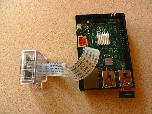
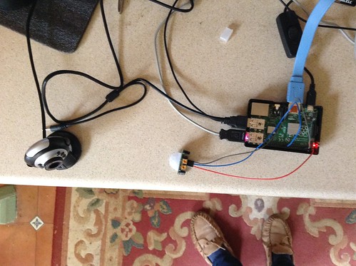
It took a couple of hours scouring the net to find all the information I needed along with lots of failed coding attempts but eventually I got the idea to work just as a test layout in the kitchen. Very few components are needed - the Raspberry Pi (B+ in my case), the USB camera and the PIR:
(clicking on a photo will open a larger copy)

IMG_0126

Of course a screen, mouse and keyboard were attached while coding.

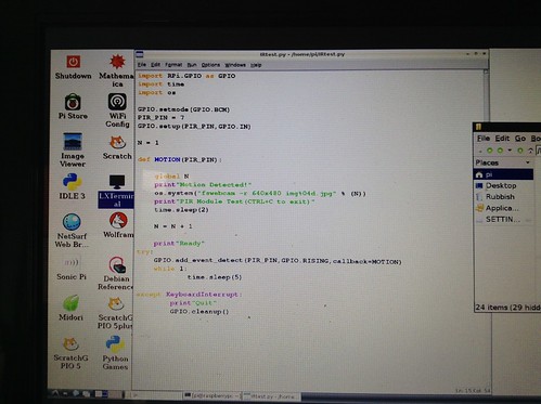
Cobbling together several pieces of code from different sources resulted in:

IMG_0124

modules loaded:
GPIO to acces the pins
time to be able to add delays where needed
os to give access to fswebcam code

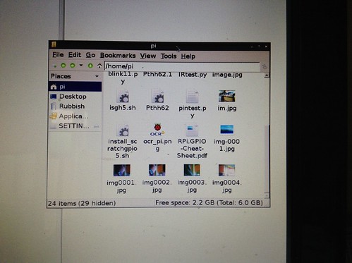
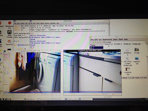
N is a numerical counter which increments each time a photo is saved and added as a four digit number to the file name.

IMG_0125

IMG_0127

Next will be to get the photos saved on a USB stick instead of the micro SD card.


Saturday, 20 September 2014

BerryClip+

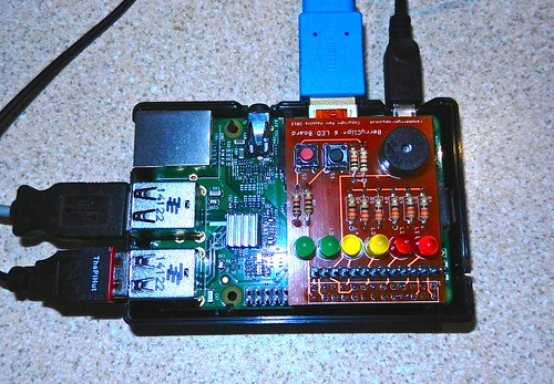
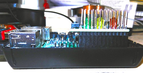
I ordered a BerryClip+ kit of parts from Ryanteck Ltd. In one of my fastest Round Tuits I had all the parts soldered in about an hour. Included in the parts are 6 LEDs, 2 push switches and a buzzer. The BerryClip+ is the red board:

BerryClip+  DSCN3468

By going to raspberrypi-spy.co.uk it is possible to download instructions as none come with the kit. Included in those are details of how to download a set of Python test files so all available facilities on the board can be tested.

It was a great relief when all 10 test files worked perfectly first time.
Here are two of them in operation:


For non morse readers the message should read "hello from m1btr"  (my amateur radio callsign).
The morse message is typed into the RPi and then the routine sends it in morse to the red LEDs and the buzzer.

Sunday, 14 September 2014

The Ups and Downs of a USB Camera

As I keep having problems with the RPi camera I've been having a play with USB cameras on the Raspberry Pi B+.  I have a couple of oldish USB cameras I used a few years ago when I used Skype. They both work on the RPi OK once fswebcam is installed. I also have the RaspiCam Remote app installed on a Samsung Galaxy Tab2 so that the photos can be sent from the RPi to the tablet through my wifi network.

RaspiCam Remote just needs the IP address of the RPi to make a connection and load shots from the USB camera. I find it's a bit temperamental and needs re-starting from time to time, especially after the Samsung goes to sleep.

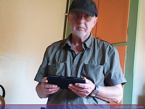
The setup was tested with everything set up in the kitchen and the pictures from both cameras were reasonably good.

USB camera 1410610257699

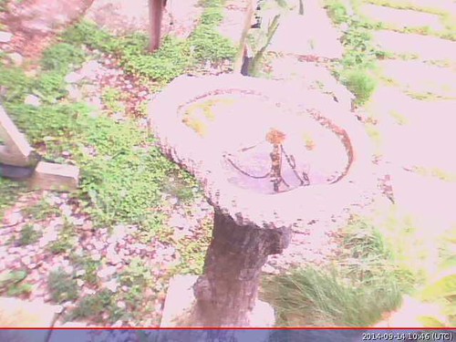
What I was hoping to do was set up a USB camera with the RPi in the Summerhouse so it could look through a side window at the bird bath. Unfortunately it would appear that USB cameras are probably set up to work in relatively low light indoors and both were overwhelmed in daylight, even when it was cloudy:

USB camera

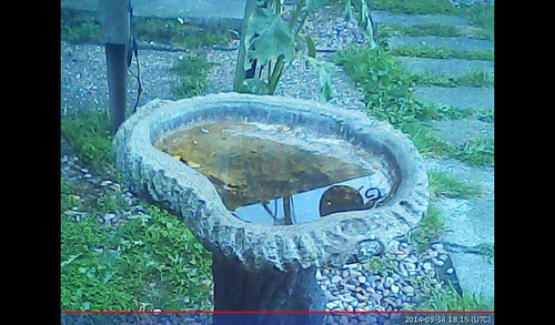
Once daylight had partly faded the results were better:

USB camera

I will have to have a long think, experiment some more and do some searching. The present setup would probably be OK on dull days in the Winter.

Saturday, 23 August 2014

LCD Master Board for Raspberry Pi

About a week ago I bought a board from Pridopia which can interface 16x2 and 20x4 LCDs or a Nokia 84x84 LCD screen. The latter came with the board with some instructions as to what software needed to be installed to dive it. Also there is a disk image containing everything on their web site. There are three variations of the image depending on which Pi board you own. Naturally I downloaded the B+ image and 'burned' it on a 8GB micro SD card.

All the examples shown use the Scratch programming program.

First thing to note is that the board catches on the extra USB ports on the B+ so it is advisable to use something, electrical tape or in my case a bit of cardboard to make sure nothing on the board makes contact with the metal USB ports. Also because of these the board does not fit fully flat on the GPIO pins but does work.
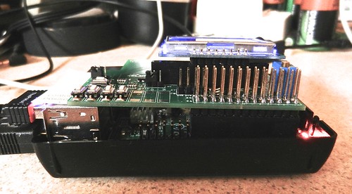
DSCN3217

My first attempt to get any text on the 5110 was a partial failure. There is an example program to show an RSS feed, providing the Pi has internet access. This worked but attempts to put my own text on the screen were a complete failure. It may have been that I was also letting the Pi update all its files, which can take ages, which was interfering with things.

I put it aside for a day and then had another attempt. Once the updates had finished things started to work as expected. I find the Scratch screen difficult to read. Others have noted the same. It is a pity that there seems to be no way to enlarge the text in that program. In the end, after much experimenting I had a working test program:
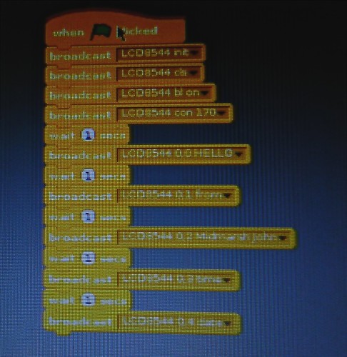
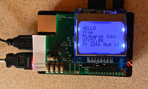
DSCN3215DSCN3208


The main thing I found out about the 5110: It is slow to respond and needed a pause between instructions otherwise they got mixed up. In the above program / script there is a WAIT 1 between each instruction which sends text to the LCD. This pauses one second.


After some experimentation I found the wait could be reduced to 0.3 seconds. Anything shorter than this caused corruption as instructions blended together.

Don't blame me for it showing 22th instead of 22nd. I just send the instruction 'date'. How it displays is decided by the inner working of the program code.

Monday, 11 August 2014

First bit of FUZE BASIC

The aim was to get the MyPiFi LED board working on the RPi B+ with FUZE BASIC. I don't have the FUZE hardware, just running the B+ with keyboard, mouse and HDMI TV as monitor.

Firstly the MyFiPi board overhangs some of the extra pins on the B+ board, as will probably be the case with most, if not all, boards designed for the RPi A and B boards. It does not touch them so is not a problem, unless you need to use the hidden pins.

DSCN3183

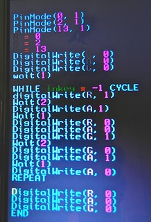
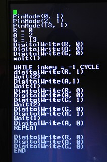
FUZE BASIC seems to have its own method of numbering the GPIO pins. The example Python scripts use 11 for Red, 13 for Amber and 21 for Green. These numbers didn't work in FURZE Basic so I wrote a short program to cycle through all the pins and noted down which pin worked which LED. Then I could get down to writing my first working program to cycle the LEDs in the traditional UK traffic light cycle:

DSCN3182      DSCN3185

I couldn't use the full colour names as some are reserved words.

Anyway, after a few attempts and correcting a few errors it finally did what it was supposed to do.
The code allows for the program to be stopped and all LEDs switched off by holding down any key on the keyboard  (WHILE inkey = -1 CYCLE)


Saturday, 9 August 2014

A Bit of Soldering

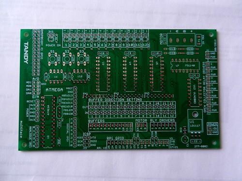
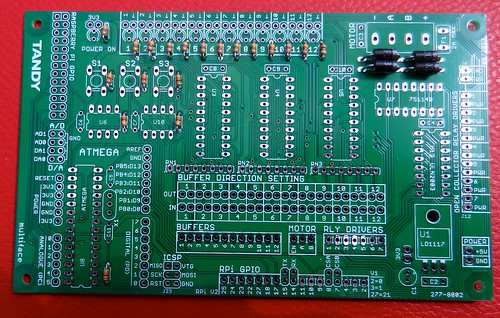
Made a start soldering some components on the Tandy Mulitface board.

Bare board:
DSCN3159

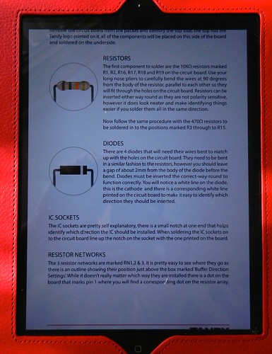
As the instructions are in the form of a downloadable pdf file I put it on the iPad so I could easily see what to do next:
DSCN3160

Resistors and diodes fitted:
DSCN3164

So far it is going a lot easier than I thought it would as the solder pads can look very close together. For the resistors I was able to use a 12W iron with a narrow bit but the diodes soaked up the heat too fast so I had to resort to a 15W with a larger bit for them.

I gave up after that as my eyes were beginning to go out of focus!

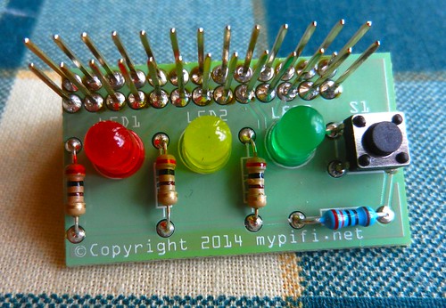
Later another small kit arrived, the MyPiFi LED board, so I decided to put that together. This is a simple board with three LEDs and a switch. Useful for me to test out a bit of programming:

DSCN3165

The example scripts are for Python but I typed one in and kept getting syntax errors when I ran it. I think I may be short of a couple of GPIO files there.

I also tried it in FUZE BASIC and eventually got the LEDs working. Just got to get the switch working then I'll explain the differences that need to be make to pin allocations for it to run in FUZE.

Raspberry Pi B+

I have looked at the Raspberry Pi on and off since it was first introduced but have only now got round to ordering one. As the B+ had recently been released that was what I went for. Along with the Pi I also have ordered a WiFi dongle and a camera.

DSCN3147


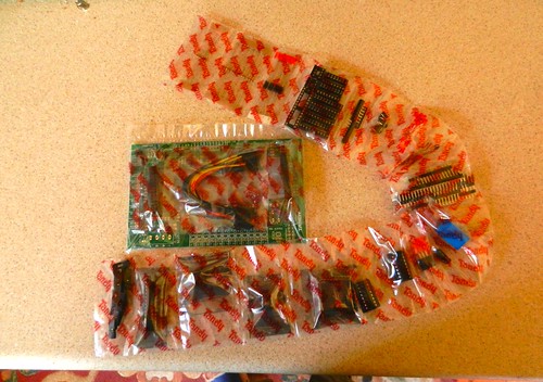
Also ordered was a Tandy Multiface kit:

DSCN3145

Previous experience of programming goes back a long way, mostly with various forms of BASIC. Sinclair BASIC on the ZX81 and ZX Spectrum, BBC BASIC on the BBC model B and GFA BASIC on the Atari ST so at least many of the structures are familiar though the remaining grey cell needs a good prodding to remember how to use them. I have reached the age where learning a new type of programming language is well and truly a very slow climb along a steep learning curve.

To date I now have two micro SD cards. One loaded with NOOBS which I have got working OK with WiFi and the camera.  The other was loaded with FUZE BASIC which works OK with WiFi but I am disappointed that there seems no way to access the camera from FUZE BASIC.